
 Generally, the cleanability of closed process equipment can already be predicted and optimized during the development phase by means of computational fluid dynamics. These computer programs calculate the flow distribution on surfaces as well as flow velocity distribution and other flow parameters such as wall shear stress (6).
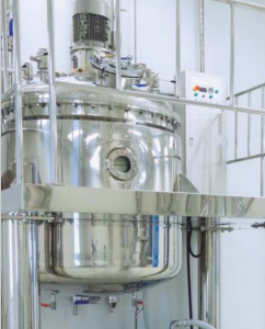
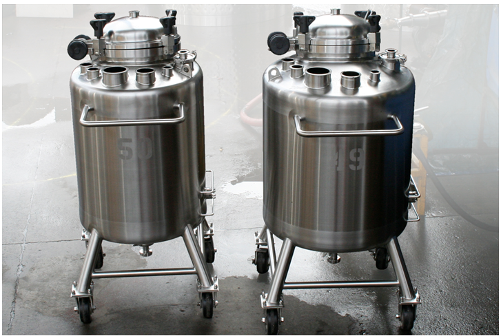
The important design criteria for vessels are:
• That the vessel is covered, and that the cover can be secured;
• The stirrer design needs to be hygienic;
• The vessel must be cleanable, typically via Clean-in-Place process (CIP);
o With CIP vessel cleaning there are choices to be made between: spray ball design or rotating jets. Rotary spray heads and sanitary spray balls, which work as rotating jets to achieve a 360° space cleaning, are superior to stationary spray balls (static spray balls do not rotate, and they require a comparatively large amount of liquid in order to generate turbulent flow);
• Hygienic fittings e.g. pressure relief, vacuum fittings;
• The attachment methods for rotors, impellers and shafts should not contain metal to metal joints or crevices;
• Totally drainable. All equipment and installation must be self-draining or drainable. Thus, horizontal surfaces shall be avoided, but sloped to one side. This principle is valid for both, product contact and non-product contact surfaces. Liquid on external surfaces need to be constructed so that they flow away from the product zone. As an example, the bottoms of tanks can be designed so that they are sloped to ensure that pools of liquid do not accumulate on the vessel bottoms.
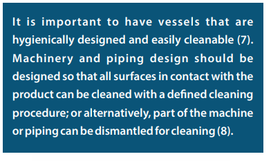
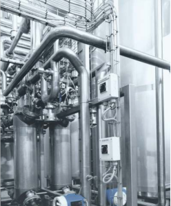
It is important to have vessels that are hygienically designed and easily cleanable (7). Machinery and piping design should be designed so that all surfaces in contact with the product can be cleaned with a defined cleaning procedure; or alternatively, part of the machine or piping can be dismantled for cleaning (8). Furthermore, a ‘Cleaning In Place’ (CIP) procedure can only be applied successfully, with reproducible results, provided all equipment to be cleaned has been designed according to the appropriate hygienic design principles. Through this, it can be ensured that all surfaces with product contact are covered by the CIP media flow and that the flow velocity at the critical points is sufficient to develop the necessary forces to clean off all product residues. Additionally, inside hygienic equipment there are no dead flow zones which – under certain circumstances – can be responsible for a continuous aggravation of microbiological parameters during production.
 In terms of assessment, this is addressed by cleaning validation (the methodology applied to give the assurance that a cleaning process has removed residues and contaminants from a piece of equipment or machinery). Cleaning is assessed based on the level of residues that remain (either chemical or microbial), either those directly found on the equipment or those indirectly contained within the final rinse after water has passed through or over the equipment and from surface sampling at selected locations. Whether the residues remaining have been reduced to a satisfactory low level is based on predetermined acceptance criteria.
With the cleaning process, be that using spray balls or jets, it is important to assess the risk of any blockages and shadowing, which can occur behind baffles, agitators. A further consideration is the drying method. Considerable risks arise through wet equipment, especially if any microorganisms survive or where the equipment becomes re-contaminated. The major microbial risk group is with Gram-negative bacteria; these microorganisms only require minute amounts of nutrients to multiply (the presence of fouling also reduces heat transfer). To avoid re-contamination, cleaned and dirty equipment must be segregated.
Additional features of a CIP system include the roles and type of vessel cleaning machines, selecting the appropriate cleaning fluid recipe and achieving the required flow rate to establish a turbulent cleaning fluid flow using adequate velocity. Effective CIP systems depend on the process being designed with hygienic design principles in mind and not as an afterthought.
Related to cleanability is the ability of the vessel to drain, which is an important element for the avoidance of wet equipment. To make it possible to remove all chemicals or water from process equipment, the equipment must be designed to be self-drainable. To achieve this, the surfaces and pipes should not be completely horizontal, but slope toward drain points. There should be no ridges that may hamper draining. Where it is not possible to build equipment in such a way that proper draining is possible, procedures must be designed to ensure that residues of cleaning and disinfection liquids or residual water can be removed in another way.
In terms of drainage:
• Internal radiuses should be larger than 3 mm,
• Minimal slope should be 1% longitudinal and cross on all areas,
• The outlet diameter should be appropriate for easy and safe connection to the gully body or pipe system,
• A special design of outlet will allow easy drain of all wastewater out of channel.
In terms of other design criteria, the layout of the top rims of product-containing equipment must avoid ledges, where product can lodge and that are difficult to clean. Open-top rim design must be rounded and sloped for draining. If the top rim is welded to the wall, the weld should be flush and polished (which will provide for a smooth surface). Furthermore, the rim must be totally closed, and the weld must be continuous, and any holes must be sealed by welding, gaskets or plastic caps.
Stirring of vessels
Vessels which are stirred are commonplace in the pharmaceutical sector and a variant of the Reynolds number (discussed in the in the context of pipes below) can be used. In a cylindrical vessel stirred by a central rotating paddle, turbine or propeller, the characteristic dimension is the diameter of the agitator (D). The velocity V is ND where N is the rotational speed in rad per second. Here the Reynolds number is: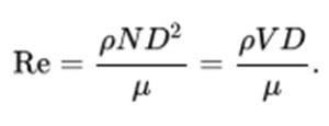
In terms of acceptance criteria, the system is fully turbulent for values of Re above 10,000.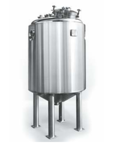
 With pipe welding, orbital welding is preferred over manual welding. Orbital welding provides precise control of the heat input into the weld that cannot be duplicated with manual processes and generally results in better corrosion resistance than manual welding (10). With orbital welding, the arc is rotated mechanically through 360° (or 180 degrees in double up welding).
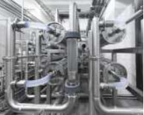
In relation to design, it is desirable for piping systems to be designed to minimize the number of clamp or hygienic (sanitary) connections and fittings and, if practical, piping systems should be installed in which all the joints are welded. This means avoiding flexible connections (such as for connecting piping for sterilizing or charging the vessels) and using a swing-bend design featuring all-welded connections instead. This type of example design minimizes also helps to avoid operator error, such as with sending valuable product to waste instead of to the next process step.
 Pipe couplings must be free of crevices and be sealed with a gasket. Any seal or gasket used must not allow for soil or bacteria to be trapped. Metal to metal joints should be avoided entirely. Items like bolts or name plates should be welded to the surface and not attached via drilled holes. Exposed threats, screws, rivets and bolts should not be present in product contact zones; and sharp corners should also be avoided.
Flow rates and the Reynolds number
For use when processing, pipework flow rates should be of turbulent flow to minimize the possibility of microbial adhesion to the surface. This means seeking to achieve between 1 to 3 meters per second linear velocity. Since the velocity of fluid in pipe is not uniform across section area, a mean velocity is used for the confirmatory calculation. The nature of flow in pipe is based on the work of Osborne Reynolds, and this is dependent upon the pipe diameter, the density and viscosity of the flowing fluid and the velocity of the flow (11).
To make the final assessment the dimensionless Reynolds number is used. To assist with fluid flow, all corners should have a radius not less than 3 mm. Product contact surfaces should be finished to an appropriate roughness that is smooth enough to enable them to be easily cleaned and disinfected. The surface finish should be 0.8μm Ra or better (as discussed in relation to vessels, above).
The Reynolds number is proportional to inertial force divided by viscous force with produces a dimensionless number. This allows for an assessment of flow regimes. When assessing the Reynolds number, turbulent flow occurs when the calculation exceeds 4000. Turbulent flow needs to be assessed carefully since eddies and wakes can make the flow unpredictable; these are minimized at high flow rates and with larger pipes.
 Below the turbulent flow value, the flow is assessed as laminar and this is unsuitable for pipes used in biopharmaceutical processing. Also, to be avoided is transitional flow, which is a term used for when there is a mixture of laminar and turbulent flow; with turbulence occurring in the center of the pipe, and laminar flow near the edges of the pipe. This is due to the different speeds and conditions of the fluid in different areas of the pipe’s cross-section, depending on other factors such as pipe roughness and flow uniformity.
In terms of the Reynolds ranges for pipe flow (12):
• Laminar when the Reynolds number is < 2300
• Transient when the Reynolds number is <2300 and < 4000
• Turbulent when the Reynolds number is ≥4000
The above flow regimes represent typical flow patterns exhibited by fluids as they flow under differing conditions. The Reynolds number for fluid flowing in a circular pipe may be calculated as follows (13):
Where: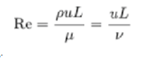
ρ is the density of the fluid (kg/m3)
u is the velocity of the fluid with respect to the object (m/s)
L is a characteristic linear dimension (m)
μ is the dynamic viscosity of the fluid (Pascals or N•s/m2 or kg/m•s)
ν is the kinematic viscosity of the fluid (m2/s).
Alternatively, the equation can be expressed as:
Re=μρVD
Where:
Re = Reynolds number
µ = Dynamic viscosity (such as Ns/m2, lbm/s ft)
ρ = Fluid density (such as kg/m3, lbm/ft3)
V = Average velocity (such as m/s, ft/s)
D = Pipe Diameter
What this equation is doing is assessing the inertia force (ρ u L) to viscous or friction force (μ)
Other pipe design factors
Some further design consideration for pipes are for them to be sloping and drainable and to have no dead legs, which refers to an area of the pipework where product can become trapped. The dead leg is typically defined as >3 times the diameter of the pipe (length of the dead leg is measured from the pipe wall of the main pipe. To assess dead legs, the term L/D often applies. With this, L is equal to the leg extension perpendicular to the ‘normal’ direction of flow and D is equal to the internal diameter of the extension or leg.
For pharmaceutical process piping systems, it is desirable to keep the dead legs to a minimum. Although an L/D of 2:1 is achievable with current design technology for valving and piping, 4:1 is considered acceptable for most bioprocess and pharmaceutical applications. A large L/D makes it more difficult to achieve a hygienic condition. This is especially notable with steam sterilization because air pockets prevent steam reaching all surfaces.
In some cases, dead legs cannot be completely eliminated, or they may continue to exit with some legacy systems. If dead legs exist in a system, some provision should be made for flushing them through. It is also important to assess whether an instrument or sampling position causes a dead leg. Ironically, this can include points to permit the taking of samples for microbiological testing, such as a hygienic water sampling point flush with pipe.
 With drainability retained fluid in the piping provides a medium where microorganisms could grow. Retained fluid could also promote corrosion, leading to product contamination. The utilization of gravity presents an effective method of removing all traces of liquid from a process system. The piping system should ideally be designed with falls or slopes to ensure complete drainability, such as ensuing that the tong runs of piping leading to drains are sloped to provide a 1:100 fall (or have a 30° slope).
 About the Author
Dr. Tim Sandle is the author of the book Digital Transformation and Regulatory Considerations for Biopharmaceutical and Healthcare Manufacturers, Volume 1: Digital Technologies for Automation and Process Improvement, available via the PDA Bookstore:https://www.pda.org/bookstore/productdetail/5897-digital-transformation-volume-1